
QR Code
Products
Contact Us


Fax
+86-579-87223657

E-mail

Address
Wangda Road, Ziyang Street, Wuyi County, Jinhua City, Zhejiang Province, China
|
Industry |
Semiconductor manufacturing (epitaxy/etching hot-zone component quality acceptance) |
|
Process |
GaN MOCVD, SiC epitaxy, incoming and on-tool acceptance of related hot-zone parts |
|
Solution |
Quantifiable acceptance framework for thickness uniformity, particles, purity and surface condition |
|
Services |
GDMS/ICP-OES reports, thickness and uniformity data, sample verification, failure analysis support |
|
Results |
• Typical thickness uniformity target: within ±5% • Particle control reference: ≤0.1/cm² order (process-dependent) • Coating purity can be below 5 ppm; some batches reach 99.99995% • Incoming metrics and report items that can be checked on delivery |
After the material is selected, what often decides on-tool performance is quantifiable metrics such as thickness uniformity, particle level and purity. This article organizes the key quality dimensions of CVD SiC coating in acceptance and use, helping move from “the specification matches” to “the report can be checked and risk can be anticipated.
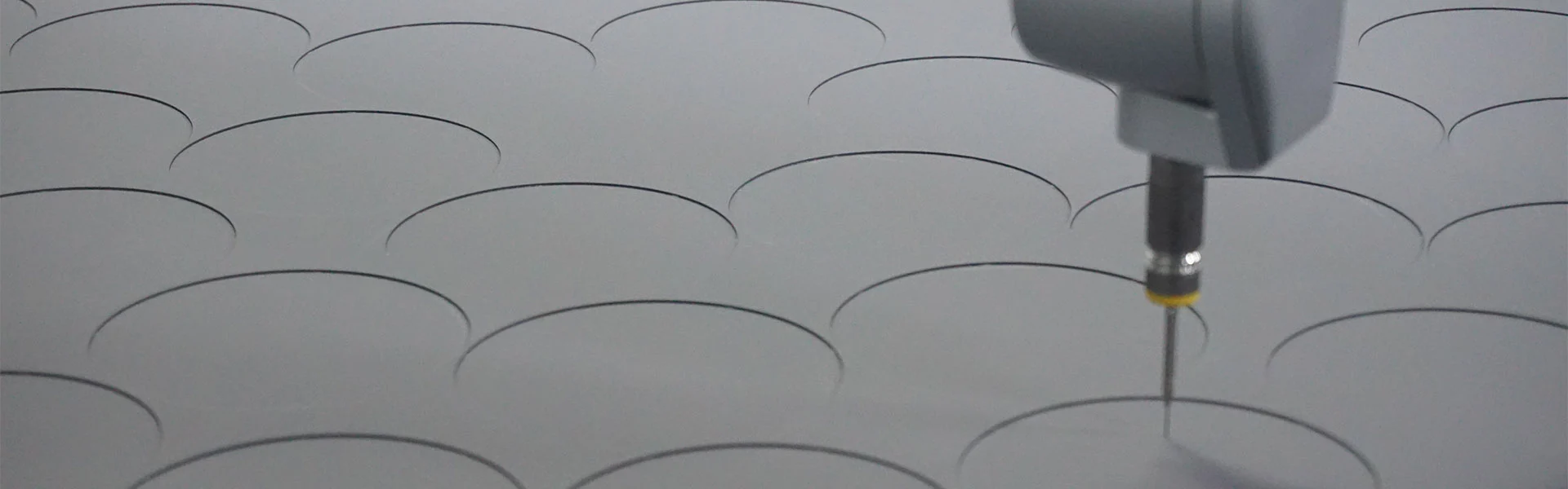
Core Conclusion: Non-uniform coating thickness changes local thermal resistance and surface condition, which in turn affects temperature uniformity and epitaxial film thickness distribution. A typical engineering target is to control thickness uniformity within ±5%, with measurement points placed in critical zones of the part—not only looking at the average value.
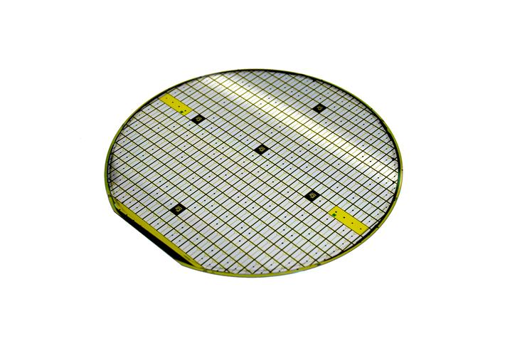
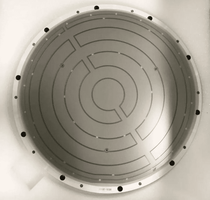
For hot-zone parts such as susceptors and preheat rings, the coating is both a chemical barrier and part of the thermal path. Under the same nominal thickness, large deviations between edge and center, or between grooves and flat areas, can amplify uniformity variation at the edge of the process window.
• Nominal thickness and tolerance range (matched to process and part structure)
• Multi-point uniformity (recommend covering center, edge and structural transition zones)
• Whether differences between critical and non-critical faces are within an acceptable range
Core Conclusion: Particle control cannot stop at “low particles.” It should land on surface cleanliness, density and powdering risk in use. Engineering practice often uses particles per unit area, surface roughness and coating integrity as check items at incoming and before on-tool use. A target particle level may reference the ≤0.1/cm² order and be tightened or relaxed per plant process.
Epitaxy and etching are particle-sensitive. If the coating is porous, micro-cracked, or locally too thick/thin, it is more likely to become a particle source after some use. Clarifying surface condition at incoming acceptance is more effective than assigning blame after problems appear.
• Appearance: uniform color, no obvious pits, blisters or delamination
• Whether surface roughness (Ra) is within the agreed range
• Whether particle or cleanliness statements are provided (per mutually agreed test methods)
Core Conclusion: It is recommended to treat GDMS/ICP-OES purity reports, thickness and uniformity data, appearance and critical dimensions as a standard incoming package. Coating purity can be below 5 ppm; some batches reach 99.99995%. Reports should map to specific lots and parts for traceability.
An executable acceptance list is more useful than a verbal “meets specification.” The following items can be trimmed to plant requirements and written into purchasing and IQC documents.
|
Check Item |
Description |
|
Lot and report mapping |
Report number matches physical lot; traceable |
|
Purity (GDMS/ICP-OES) |
Critical impurities within agreed limits; coating purity can be below 5 ppm |
|
Thickness and uniformity |
Nominal thickness met; typical uniformity target within ±5% |
|
Appearance and surface |
Uniform color, no visible defects; Ra within agreed range |
|
Critical dimensions |
Match drawing or OEM spare tolerances to ensure tool fit |
Before on-tool use, sample verification of temperature uniformity and particle performance is still recommended. A passing report does not guarantee optimum performance inside the process window, but it can greatly reduce the chance of releasing a defective lot to the tool.
Core Conclusion: Write thickness uniformity, particles/surface and purity into executable acceptance clauses, and require reports to map one-to-one with lots. When anomalies occur, first compare other tools on the same lot and process changes, then decide whether to upgrade the material solution.
Recommended sequence:
1. In the purchase specification, define thickness tolerance, uniformity target, purity method and limits, and appearance requirements.
2. At incoming, check report against physical lot; sample critical dimensions and appearance.
3. After a new lot or process change, run a small batch on tool to check particles and uniformity.
4. When lifetime or particles are abnormal, investigate coating data and furnace/process conditions in parallel; avoid single-cause attribution.
Core Conclusion: Reporting only the average thickness is not enough. Local thinning or thickening at the edge and structural transition zones directly raises particle and thermal field risk. Acceptance must specify multi-point uniformity and measurement locations—not only whether the disk-average falls inside the nominal tolerance.
Engineering Note:
After a SiC epitaxy line introduced a new-specification CVD SiC coated susceptor, IQC checked the supplier report: nominal thickness and disk-average thickness were both within the agreed tolerance, GDMS purity passed, and appearance showed no obvious anomaly, so the lot was released to the tool. After about twenty runs, some trays repeatedly showed rising particles and local film thinning in the wafer-edge corresponding region, while other trays from the same lot performed normally. Process gas distribution was suspected at first, but when the same chamber was switched back to the old-specification trays, the edge issue clearly subsided, pointing to the new lot itself. Multi-point thickness measurement on failed parts versus same-lot normal parts then showed: the disk average was indeed in spec, but outer-ring near-edge points were systematically about 8%–12% thin, already beyond the plant’s internal uniformity target of ±5%; the thin zones highly overlapped the high-particle zones. Root cause was traced to deposition rate in the grooves and outer ring not being fully calibrated for that structure; the outgoing report provided only the average, without the agreed multi-point distribution. The line then wrote “center + edge + groove transition” multi-point uniformity into mandatory incoming checks and required reports to include a measurement-point map. After the supplier adjusted the outer-ring process window on subsequent lots, edge particles and film-thickness variation returned to historical levels. This case shows: average in spec does not mean uniformity in spec. For thermally sensitive susceptors, acceptance without multi-point thickness and location data can let local defects onto the line. Writing measurement-point layout and a uniformity target such as ±5% into the specification is more effective than arguing afterward whether “the report was acceptable.”
1. Is ±5% thickness uniformity a mandatory standard?
It is a common engineering target, not a unique legal standard. A tighter or slightly wider range can be agreed with the supplier based on part structure and process sensitivity. What matters is measurement-point coverage and report traceability.
2. Does ≤0.1/cm² apply to all processes?
It is a reference order of magnitude. Final criteria should follow the plant’s chamber, process and yield requirements, with test method and judgment rules written into the specification.
3. Is a purity report alone enough?
No. At minimum, purity, thickness/uniformity and appearance (plus agreed surface metrics) should be available together; dimensional match also affects on-tool use.
4. What if the report passes but on-tool particles are still high?
First compare other tools on the same lot, recent process/maintenance changes and cleaning status, then assess whether the coating solution or process window needs adjustment. Cross-check with the selection-decision and equipment-compatibility cluster pages if needed.
5. What quality-related support can VeTek provide?
GDMS/ICP-OES and similar analysis reports, thickness and uniformity data, sample verification, and technical communication on anomalies (including in English) can be provided.
After the right material is chosen, thickness uniformity, particle control and purity decide whether a given lot can enter the process window stably. Writing these three into checkable acceptance clauses and insisting that reports map to lots is the most direct way to reduce on-tool risk.
If you need acceptance metrics for a specific part or help interpreting reports, you are welcome to contact the VeTek technical team. Dr. Xiao and the engineering team can assist with specification alignment, sample verification and anomaly analysis.
For selection logic, see: VETEK | How to Select SiC Coating, TaC Coating or Solid SiC by Process Conditions; for the full framework, see the pillar page Performance Boundaries of CVD SiC, TaC and Solid SiC in Epitaxy and Etching Processes.
Main References and Data Sources
1. VeTek Semiconductor internal engineering and customer acceptance practice.
2. Metric descriptions on purity, thickness uniformity and particle control in the CVD Coating Consumables Selection Engineering Handbook for Semiconductor Epitaxy & Etching Equipment.
3. VeTek official website product and technical materials: https://www.veteksemicon.com/silicon-carbide-coating
Note: Uniformity, particle and purity figures in the text are typical engineering references; actual values follow contract specifications and measured results.
Author: VeTek Semiconductor Technical Engineering Team (completed under the guidance of Dr. Xiao)
For further technical discussion or sample evaluation, please contact us via the official website.
+86-579-87223657
Wangda Road, Ziyang Street, Wuyi County, Jinhua City, Zhejiang Province, China
Copyright © 2024 WuYi TianYao New Material Tech.Co.,Ltd. All Rights Reserved.
Links | Sitemap | RSS | XML | Privacy Policy |