
Tech &  solutions

VETEK | How to Select SiC Coating, TaC Coating or Solid SiC by Process Conditions

Industry

Semiconductor manufacturing, technical ceramics (epitaxy / etching / PVT crystal growth)

Process

GaN MOCVD, SiC epitaxy, SiC PVT crystal growth, plasma etching

Solution

Match by temperature / atmosphere / process: CVD SiC coating, TaC coating or Solid SiC components

Services

Selection consulting, process window evaluation, sample verification, inspection reports, thermal field matching recommendations

Results

• Conventional epitaxy ≤1600°C: prioritize CVD SiC coating

• >2000°C or highly corrosive atmosphere: shift to TaC coating

• Etching and ultra-clean critical parts: prioritize Solid SiC

• Provides actionable temperature-atmosphere-process matching logic

This article outlines the application boundaries and typical scenarios of CVD SiC coating, TaC coating and Solid SiC by temperature, atmosphere and process type, helping epitaxy and etching engineers quickly align process windows during selection and avoid particle and lifetime risks from material–condition mismatch.

1. How Does the Temperature Window Determine the Applicable Boundaries of SiC and TaC?

Core Conclusion: CVD SiC coating remains structurally relatively intact below about 2000–2100°C; beyond this range, incongruent evaporation becomes more likely and particle risk rises. TaC coating has a melting point of about 3880°C and can still maintain very low vapor pressure in PVT environments above 2400°C, making it a more robust choice for ultra-high-temperature scenarios.

Temperature is the first gate in selection. GaN MOCVD and most Si/SiC epitaxy processes usually fall within the comfort zone of SiC coating; higher-temperature, longer-cycle hot zones such as SiC PVT crystal growth require reassessing whether SiC is still adequate.

Temperature Boundary of SiC Coating

Below about 2000–2100°C, CVD SiC coating can maintain structural integrity and relatively low particle levels. As temperature rises further, preferential silicon volatilization (incongruent evaporation) aggravates surface roughness and powdering risk, putting both coating lifetime and cleanliness under clear pressure.

High-Temperature Advantage of TaC Coating

TaC has a melting point of about 3880°C and can still maintain very low vapor pressure and good chemical stability in PVT crystal growth environments above 2400°C, making it suitable as a protective coating for ultra-high-temperature graphite hot-zone components. When the process clearly enters a range where SiC cannot serve stably, switching to TaC is often more effective than simply thickening SiC.

2.How Do Atmosphere and Corrosivity Affect Coating Selection?

Core Conclusion: Under conventional epitaxy atmospheres containing NH₃, H₂ or chlorine-based gases, SiC coating usually performs well; in high-temperature hydrogen and highly corrosive environments, the corrosion rate of TaC is significantly lower (literature and engineering data indicate it can be about 1/6 that of SiC in high-temperature ammonia, and even lower in hydrogen). Reassessment against the actual atmosphere is required.

Even when temperature is still within the acceptable range for SiC, atmospheric corrosivity may become the deciding factor. Process gas species, partial pressures and cumulative exposure time all affect coating surface condition and lifetime.

Conventional Epitaxy Atmospheres

In common conditions such as GaN MOCVD and Si epitaxy, CVD SiC coating already has extensive mature use under NH₃/H₂ systems. With good control of thickness uniformity and density, thermal stability and particle control can be achieved together.

Highly Corrosive or Extreme Atmospheres

When the atmosphere attacks SiC significantly, or long exposure at higher temperature is required, the chemical inertness and lower corrosion rate of TaC become advantages. Selection should combine the plant’s gas recipe, temperature profile and historical failure modes, rather than looking only at a single temperature metric.

3.Which Scenarios Are Solid SiC and Coated Graphite Parts Suited for Respectively?

Core Conclusion: Coated graphite parts cost less and respond thermally faster, suiting most epitaxy susceptors and preheat rings; Solid SiC has no coating–substrate interface and stronger plasma resistance, suiting critical etching parts such as focus rings and scenarios with very high particle and lifetime requirements.

Solid SiC and “graphite + coating” are not a simple substitute relationship, but a trade-off of application scenario and TCO.

Applicable Scenarios for Coated Graphite Parts

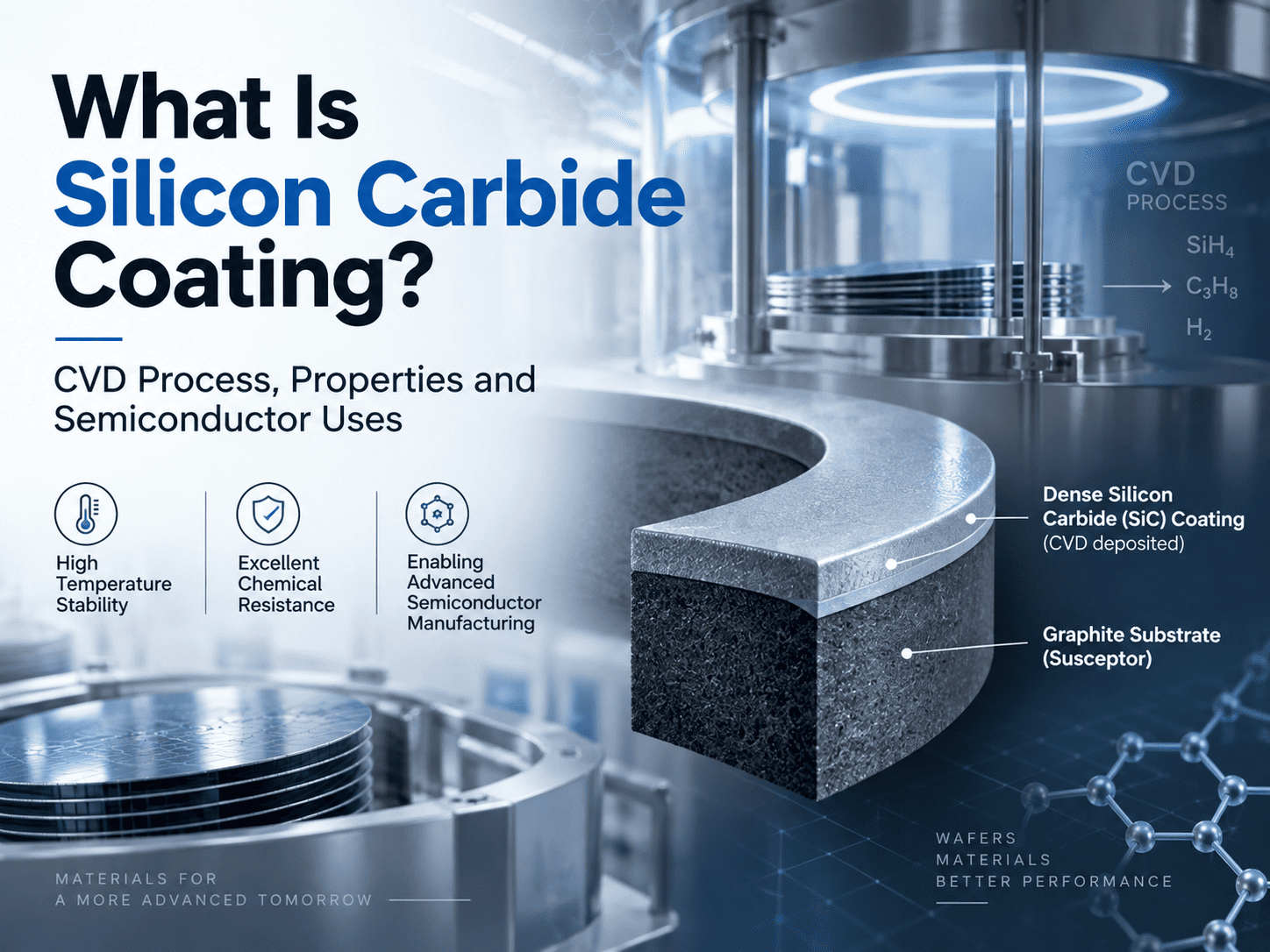
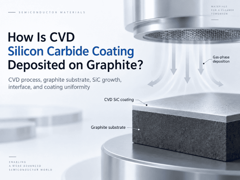
The substrate has high thermal conductivity, fast heat-up and controllable cost; CVD SiC or TaC coating provides a chemical barrier and particle suppression. Suitable for large-size susceptors, preheat rings and other parts in GaN/SiC epitaxy that need good thermal uniformity.

Applicable Scenarios for Solid SiC

The bulk is β-SiC with no coating interface and no delamination risk; purity can reach 5N–7N, with outstanding resistance to plasma attack. Suitable for critical etching chamber parts such as focus rings and showerheads, and for lines that want significantly longer replacement cycles and lower particle risk. Lifetime under suitable processes can reach the 2000+ hour range.

4.A Simplified Decision Path for Selection

Core Conclusion: First check whether temperature exceeds the stable window for SiC, then check atmospheric corrosivity, and finally choose between coated graphite and Solid SiC according to part function and particle/lifetime requirements.

A quick judgment sequence:

1. Is temperature sustained above about 2000–2100°C? If yes, prioritize evaluating TaC or Solid SiC.

2. Does the atmosphere attack SiC significantly (high-temperature H₂, highly corrosive gases, etc.)? If yes, increase the weight of TaC.

3. Is the part a critical etching component or zero-tolerance for interface delamination? If yes, prioritize Solid SiC.

4. For other conventional epitaxy hot-zone parts, CVD SiC coated graphite parts usually remain the balance of performance and cost when purity, thickness uniformity and density are well controlled.

Brief Comparison of the Three Options

Dimension

CVD SiC Coating

TaC Coating

Solid SiC

Typical temperature window

Approx. ≤2000–2100°C

Up to 2400°C+

Depends on part & process

Strong corrosion / high-T H₂

Usable; control lifetime

Preferred

Case by case

Interface delamination risk

Yes (coating–substrate)

Yes (coating–substrate)

None

Typical applications

Epitaxy susceptor, etc.

PVT hot zone, etc.

Etch focus ring, etc.

The table shows common engineering judgment dimensions; actual decisions still require verification against equipment, gas recipes and in-house failure history.

5.Case Study: A Materials Selection Review of Premature Epitaxy Susceptor Failure

Core Conclusion: Falling within the “usable” temperature range for SiC does not mean falling within the “stable” range. When a process combines elevated temperature with a strongly reducing atmosphere, selecting only by temperature ceiling tends to underestimate corrosion and particle risk; atmosphere and historical failure modes should be included in the decision.

Engineering Note:

After a GaN/SiC epitaxy line switched to a higher-temperature recipe, a batch of CVD SiC coated graphite susceptors that had previously been stable began to show edge roughening and rising particle levels at about two-thirds of their historical lifetime. Replacement cycles were forced shorter and yield variation increased. Early investigation focused on coating thickness and purity: GDMS and thickness uniformity were both within outgoing specification, and the same coating batch still approached historical lifetime on other tools, so a materials-batch issue was largely ruled out. Further comparison with process-change records showed that the new recipe raised peak temperature by only about 80°C—still near the lower edge of the common SiC window—but hydrogen partial pressure and high-temperature hold time increased significantly, amplifying reductive attack on SiC inside the chamber. Surface and cross-section comparison of failed parts versus same-batch parts without anomaly showed more concentrated coating thinning and micro-roughness in the high-temperature zone, consistent with corrosion features after the atmosphere was strengthened. The line then ran a small-batch verification with a TaC coating solution under the same hot-zone structure; under the same recipe, particles and replacement cycles returned to acceptable levels. This case shows that selection cannot only ask “is temperature still within the range where SiC can be used,” but must also ask “under the current atmosphere and hold time, is SiC still the lower-risk choice.” When temperature is raised together with a strongly reducing atmosphere, even if the nominal temperature ceiling is not breached, TaC should be reassessed or the process window adjusted, rather than defaulting to the previous coating solution.

6.FAQ

1). What is typically selected for conventional GaN MOCVD processes?

In most cases, prioritize high-purity graphite + CVD SiC coated susceptor/preheat ring. When temperature and atmosphere fall within the SiC comfort zone, performance and cost can both be managed.

2). When must TaC be considered?

When temperature is sustained above about 2000°C, or when the atmosphere attacks SiC significantly (e.g. certain PVT and highly corrosive conditions), prioritize evaluating TaC coating.

3). Is Solid SiC always better than coated graphite?

No. Solid SiC has advantages in no-interface, plasma resistance and some ultra-long lifetime scenarios, but costs more; most epitaxy trays still use coated graphite. Choose by part function and TCO.

4). What still needs verification after selection?

It is recommended to verify temperature uniformity, particle levels and actual lifetime with samples on tool before deciding volume. The material name alone is not enough to guarantee line performance.

5). How does this connect to equipment compatibility and custom replacement?

After the material is selected, dimensional and thermal field matching must still be done for the specific equipment model. See the cluster page Aixtron and Veeco Graphite Susceptor Compatibility and 1:1 Custom Replacement Solutions.

7.Summary and Next Steps

The key to selection is aligning the process window: temperature sets the boundary, atmosphere sets corrosion risk, and part function decides whether Solid SiC is needed. Getting these three steps clear, then combining with sample verification, is more robust than simply pursuing a “higher specification.”

If you are matching SiC coating, TaC coating or Solid SiC solutions to a specific tool and process, you are welcome to contact the VeTek technical team. Selection advice, sample support and inspection reports can be provided. Dr. Xiao and the engineering team can assist with process window and thermal field requirements.


Main References and Data Sources

1. VeTek Semiconductor internal engineering data and customer process window practice.

2. Material boundaries and lifetime references from the pillar page CVD Coating Consumables Selection Engineering Handbook for Semiconductor Epitaxy & Etching Equipment.

3. VeTek technical article: SiC vs TaC coating performance comparison and high-temperature stability discussion.

4. Nakamura et al., Applied Physics Letters, 2015 — Protective performance of TaC coating in high-temperature, highly corrosive environments.


Note: Temperature and lifetime ranges in the text are typical engineering references; actual values should follow in-house process and measured verification.

Author: VeTek Semiconductor Technical Engineering Team (completed under the guidance of Dr. Xiao)

For further technical discussion or sample evaluation, please contact us via the official website.


X
We use cookies to offer you a better browsing experience, analyze site traffic and personalize content. By using this site, you agree to our use of cookies.Privacy Policy
RejectAccept